Howdy, friends! I’ve been building Ben Eater’s 8-bit computer so that I can better understand the electronics behind computers and low-level code execution. It’s a pretty good kit, and I’m having a great time doing it. Let me walk you through how I went about doing it.
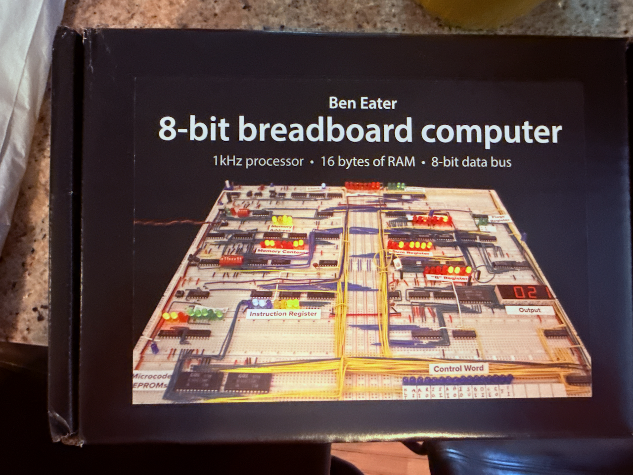
The parts all showed up in this lovely box:
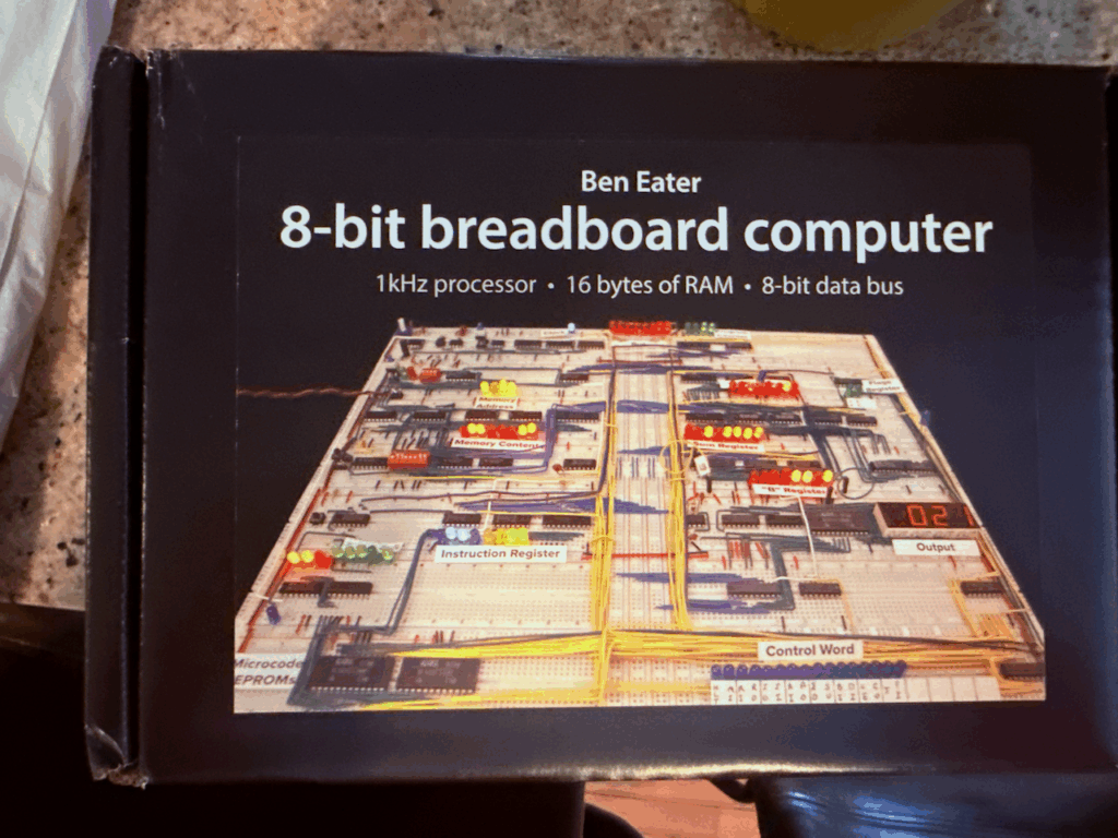
It had everything I needed in it, though there were some differences that I had to adapt to.
Part 1 – Astable 555 timer
Note: My kit didn’t include the 100kΩ resistor, I had to pull one from my collection. Also, the variable resistor in my kit was different from the one he used (it doesn’t want to sit still in the breadboard). Also, while in the video it shows his capacitors being off (he tests what he thought was a 1µF capacitor and it actually read as 2µF), the ones he includes in the kit are the correct 1µF value.
This part was mostly straight-forward, and I was able to move through it pretty quickly. I set up my breadboard pretty quickly and then got to work wiring up the capacitors, and the variable resistor. This is when I tried hooking my oscilloscope up to the circuit to see if I could replicate Ben’s noise issue. But first, a word on F-NIRSI oscilloscopes.
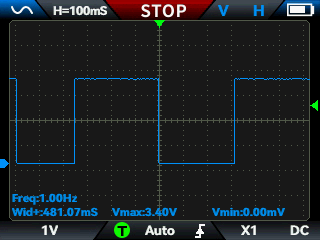
I have two F-NIRSI pocket oscilloscopes: the TC3 and the TC4. Both of them are pretty decent for just making sure the wave form and parameters you’re looking for are present. What they’re not good for, however, is showing you the fine-detail in various oddities of analog voltage changes over time. Also, they’re both single-channel scopes, so you can only watch one signal at a time. If I look at just the output signal on the 555 timer we configure in part 1, here’s what I see on my F-NIRSI TC4.
Let’s contrast this with what I get from my Digilent Analog Discovery 3.
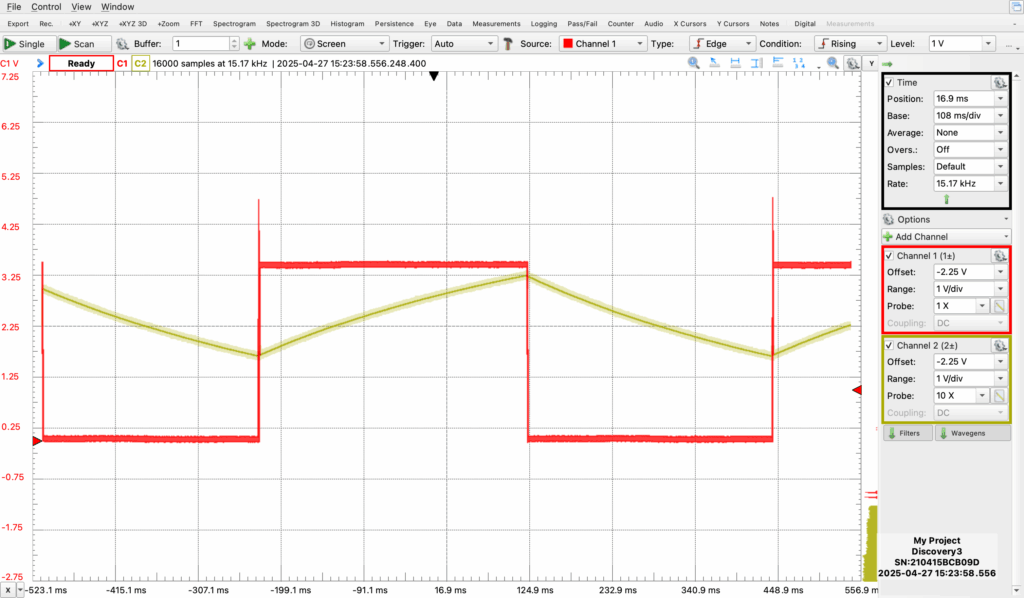
The red line is the output, tracking the same signal as what the F-NIRSI showed. Not only does this also have the capacitor’s charge curve on channel two (which was really neat to see, and helped me troubleshoot as I tried different variable resistors), but it also shows you the pointy tip of the leading edge of the curve where voltage goes up before stabilizing at about 3.3V. Ultimately, I was unable to fully replicate the noise that Ben was seeing in his video, but I was able to see the over-shooting. Tying pin 5 to ground via the 0.01µF capacitor did the trick for me here, too.
Part 2 – Monostable 555 timer
Every engineer of any kind has learned (usually through pain) that it’s important to put some forethought into our designs. Ben offers us some of that in this part because the monostable clock allows us to manually step through instructions later on when the clock is actually driving a computer which is running code. What is it? It’s a button that sends clock pulses!
While you probably could get away with just using a simple button, Ben shows us how to debounce this signal using a second 555 timer IC. This portion of the program is pretty straight-forward, and when you’re done you end up with something that looks like this:
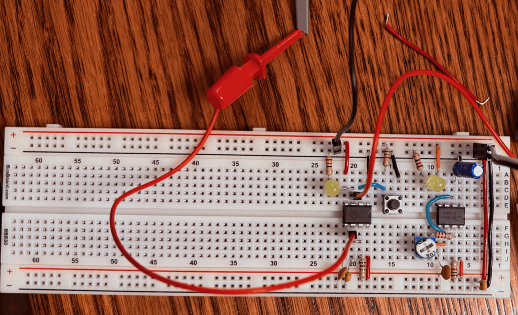
You can see my oscilloscope probes here on pins 3 and 6, watching both the output and the charge curve on that 0.1µF capacitor.
Tip for fellow n00bs: If you’re trying to watch the charge curve on the capacitor for this part with your oscilloscope, you’ll want to switch to 10X mode on your probe. When I tried using 1X, the capacitance of the probe prevented the voltage on pin 6 from dropping (ever), and the SR latch was just always engaged. Switching to 10X mode, with reduced capacitance and resistance, allowed me to see the much more delicate charge curve without interfering (as much) in the circuit.
Part 3 – Bistable 555 timer
This part of the clock module is here to help us switch between the astable and monostable clocks. In the video he uses a latching tactile switch, but I used an unused double-throw switch that I salvaged from the clock I am using for a different project for fitment reasons. This portion of the program isn’t terribly different from the other two, but it is somewhat counter-intuitive when he gets to the deboucing on the switch itself.
You see, it is known that a hacker in possession of a 555 timer IC will be in want of more 555 timer ICs, and that’s no different here as Ben uses a third 555 timer IC to de-bounce this switch. Instead of using capacitors and resistors for timing, though, Ben takes us on a journey where we try to limit our use of this 555 to just hijacking its SR-latch.
We do this by:
- Setting the trigger to the switch
- The output of the double-throw switch is wired to pin 2
- Add a 1kΩ pull-up resistor on pin 2 to 5V so it’s high unless the switch grounds it
- Setting the reset to the other side of the switch
- Pin 4 is wired to the opposite end of the switch from pin 2
- Using a 1kΩ pull-up resistor for pin 4
- Tying pin 6 to ground so that the threshold is always low so that the transistor on pin 7 never activates
- The switch’s common lead (the middle one) is then tied to ground so that if the switch is in the downward position it latches and in the upward position it resets.
Note: My kit included a different double-throw switch, but its leads were too thick to fit into the breadboard. I had to swap it out for another part.
Part 4 – Clock logic
I’ve never used any of these types of components before, so this was one heck of a learning experience. In this portion of the program Ben shows us how to use three ICs: an inverter, an AND gate, and an OR gate. We wire it up to have three clock states:
- Astable clock pulse, with the variable speed resistor giving us some real-time clock speed control
- The monostable clock pulse, allowing us to manually step through instructions later
- A halt state, which will later allow us to give our code the ability to stop the computer when it’s finished
All of this together is a lot more complex than I ever thought it would be, but it’s really great how it works. Here’s what the clock looks like when we’re done!
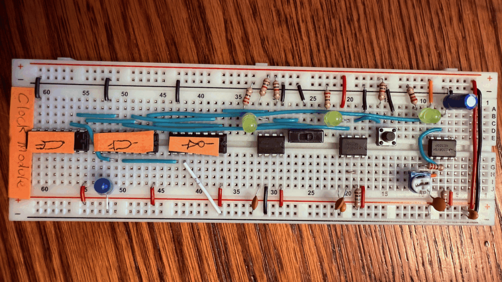
You can see I labeled the clock module, and despite my sloppy symbol drawing you can see I have (from the left to the right) the OR gate (LS32), the AND gate (LS08), and the inverter (LS04). You can see the switch in line as well, and the halt instruction is wired to pin 9 on the inverter, which when brought high prevents the clock from ever sending a pulse at all.
The ultimate output of the clock module is emitted from pin 8 (Y3) on the AND gate. Ben explains that there are certainly simpler ways of building this logic, but that this is the best way for learning (which I appreciate).
Recommendations
- I would buy an Adafruit Parts Pal before starting this kit, as well as a giant set of a bunch of resistors with different values.
- When you watch the videos, whenever Ben draws a schematic, I recommend taking notes. That saved my butt many times over.
- He does have KiCad versions of the schematics available on the site
- His hand-drawn ones are a lot easier to grok, though
- The power supply he includes in the kit is great, but I used this HW-131 power supply module which allows me to use either USB power or a barrel connector. I use a 9V battery in the barrel connector since it’s super portable and doesn’t require me to sit near a wall outlet.
- While Ben says that an oscilloscope is optional, I found it really helpful to improve my understanding of using an oscilloscope by following along.
- When he uses an oscilloscope, I try to follow along with my own oscilloscope
- I have a pocket oscilloscope, which is fine for most things
- When he was looking at the high-frequency noise in part 1, though, my pocket oscilloscope didn’t have sufficient resolution for me to see that
- I also have a Digilent Analog Discovery 3 device, which has an oscilloscope mode in the WaveForms software that they provide (no, I couldn’t find any workable alternatives)
- I recommend you also follow along if you’re not comfortable using an oscilloscope, it’s really nice to have an example to follow
Gratitude
- A huge shout-out to my friend and colleague Ian Gallagher; he’s the one who talked me into buying the Digilent Analog Discovery 3, without which I would have learned less and understood less than I did.
- Obviously I wouldn’t have been able to do this without Ben Eater, who produced these excellent kits and tutorials. It’s really hard to learn this stuff as an adult without the ability to go back to school, and this tutorial really made a lot of learning possible, easy, and a bunch of fun.
Wrap-Up
This was a really fun part of the kit. Up next are registers and the arithmetic and logic unit (ALU). I’m stoked, but I’m also going to have to figure out where I’m going to put this thing as it grows.